Flux Chamber
Sampling of gaseous emissions from area sources
Unlike a point source, whose emissions are concentrated at a single point (e.g., a stack), an area source is in fact a source whose entire surface emits odors or gaseous compounds into the atmosphere. These sources are often made of solid piles or liquid surfaces. These emissions from such area sources must be collected using a specialized equipment, called a flux chamber.
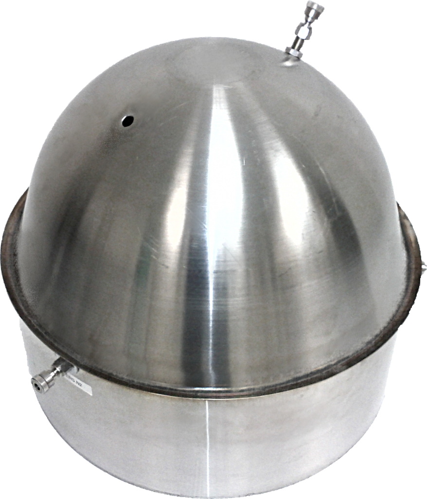
An Onose-8® flux chamber consists of a semi-sphere installed directly on the area source in order to collect the gaseous emissions escaping from the surface. A constant flow of inert gas is added inside the flux chamber in order to generate odours or gaseous contaminants by the movement of air inside the flux chamber. The use of the flux chamber allows to sample gaseous emissions from an area source without previously sampling or disturbing the emitting surface. It thus consists of a non-destructive gaseous sampling method.
Applications
The Onose-8® flux chamber by AtmoDC Inc. offers the following advantages:
- Manufactured entirely in stainless steel;
- Single-shell chamber without any cracks or joints;
- Easy to clean; thus avoiding cross-contamination;
- Equipped with 4 vents on the sides, complying with the requirements of the US EPA;
- Robust and durable
The Onose-8® flux chamber can be used, without limitation, in the following cases:
- Windrow composting;
- Wastewater treatment plant;
- Retention basins;
- Field spreading simulation of organic residual materials, according to existing standards;
- Landfill sites;
- Contaminated soil.
Download the brochure
Flux Chamber Operation
Made exclusively of stainless steel, the Onose-8® flux chamber, designed and marketed by AtmoDC Inc., meets the design criteria of the US EPA. Une chambre de flottaison peut aussi être installée autour de la chambre à flux afin de faciliter le prélèvement des émissions gazeuses d’une surface liquide. Emission sampling lines and inert gas lines of various lengths can also be mounted on the instrument. A temperature sensor port is also available on all models proposed by AtmoDC Inc.
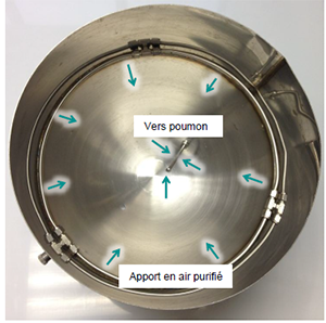
The flux chamber allows the extraction of gaseous emissions from solid or liquid surfaces emitting odors or gaseous contaminants. To be able to extract odors and contaminants from an area source, a turbulent air flow must be produced inside the flux chamber. This turbulence on the surface of the source will retrieve the odors or contaminants emitted by the surface of this source. To produce that turbulent airflow, the flux chamber must be connected to a purified air supply. This supply must be connected to the purified air supply O-ring (point C). This purified air will be distributed inside the sampling chamber (point A) via the air supply distribution line (point F). This distribution line creates a turbulent air flow over the surface of the source to be sampled. This turbulence will collect odors or contaminants from the area source.
The turbulent air containing contaminants or odors emitted from the surface source is then drawn into the sampling rod (point E) located inside the sampling chamber (point A).
This air sampled by the sampling rod will then be directed by vacuum to the O-ring of the vacuum chamber (point B) before reaching the Onose-8® sampling bag located in the Onose-8® vacuum chamber.
A 0.25-inch (6 mm) diameter Teflon® tube must be installed between the vacuum chamber O-ring (point B) located on the sampling chamber (point A) and the Onose-8® vacuum chamber.
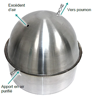
To perform an adequate sampling, the flow of fresh air supply which is distributed inside the flux chamber must be slightly higher than the sampling flow rate. The excess air inside the flux chamber will be naturally expelled outside the flux chamber through the overflow hole (point D). The overflow hole also allows to insert a temperature probe.
The following diagrams show the gas flow directions inside the flux chamber.
For any information pertaining to the purchase of this product, we will be more than happy to talk to you or answer your email. Please use the following address: info@onose.ca
Features: Flux Chamber
Product Number | ATM-SS-FC |
|---|---|
Manufacturer | AtmoDC Inc. |
Instrument | Onose-8® Flux Chamber |
Material | Stainless Steel |
Volume* | 3.401 in3 (0.0557 m3) |
Diameter | 16 in (0.406 m) |
Height | 14 in (0.36 m) |
Mass | 7.32 lb (3.32 kg) |
Flux Chamber Components
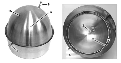
The following figure provides a detailed view of the components of the Onose-8® flux chamber. The flux chamber is composed of the following parts:
- A. Sampling chamber;
- B. O-ring towards vacuum chamber;
- C. O-ring for the purified air supply;
- D. Overflow hole;
- E. Sampling rod (inside the sampling chamber);
- F. Distribution line for the purified air supply (inside the sampling chamber);
- G. Buoyancy chamber (not shown).